After spending the last 15 years installing and commissioning winch monitoring systems, we've found that some of the most commonly asked questions are about calibration.
- How do we calibrate the LCI-90 display for tension and payout/speed?
- How often should we calibrate?
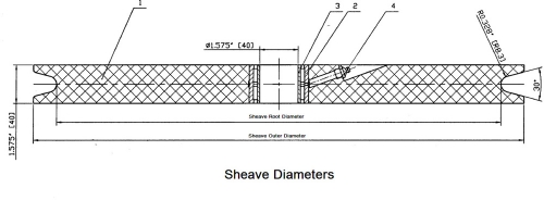
These are important questions because the calibration inherently affects the accuracy of the winch monitoring system. The following are methods we have used to calibrate the payout/speed system using our LCI-90 displays: First, once the payout has been calibrated the speed data is developed automatically as it is just a time stamp of the incoming pulses produced by the rotational sensors. As in most physical measurements with external sensors, there is a theoretical method and an empirical method to achieve the payout calibration. Let’s consider a single overboarding sheave with installed rotational sensors. The scalar calibration value used in the LCI-90 display is pulses per unit length. The theoretical calculation is to compute the circumference of a diameter defined as one line diameter plus the root diameter of the sheave. Then divide the pulse per one sheave revolution by this circumference to get a pulse per unit length. Drop this value into the display. Equation = {(line diameter + sheave root diameter) * π} / pulses per sheave revolution However this is never “exactly accurate”. The better way to calibrate your payout/speed system is to run a known length of cable through the sheave and note the accumulated pulses. With the LCI-90 we can set the display to a diagnostic screen and monitor the pulses entering the display. Through the front panel buttons reset the payout by pressing the RSET button twice quickly. Then run the known length of line through the sheave, it is best to maintain a little tension on the line as to keep it line from slipping on the sheave. When the line has passed through, note the number of pulses on the DIAG screen of the LCI-90. Then the calculation is very straight forward: Equation = number of pulses / length of line passed through the sheaves. The same line standard can be used to verify both of the procedures above. The above scenario was recently used aboard the RV Thompson to dial in the payout system on the trawl winch. They had an opportunity to compare their winch monitoring readings to a very accurate beacon and transponder unit provided by an ROV group. They discovered differences between the two systems. Once they implemented the empirical calibration technique mentioned above they were able to get both systems to match. Calibration should be done annually or as often as you detect discrepancies.