In a previous posting we discussed the technique of calibrating the payout line parameter for winch applications.
It is also important to understand the technical challenges of calibrating the tension line parameter of your winch monitoring system.
The calibration of a tension measurement system can be achieved through several methods.

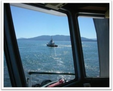
MTNW employees calibrate two Foss tugs in Puget Sound by having them pull against each other
It’s always best to conduct a live calibration of the winch monitoring system once the sensors, displays and line have been installed and the wrap angles determined and identified to be fixed (more on the wrap angle in another blog).
Since tension sensors behave in a very linear fashion, meaning that their electrical output has a linear relationship with the load applied to the sensor itself, a single, two-point calibration (a low tension and high tension reading) is often sufficient to calibrate a tension monitoring system.
We typically can calibrate a system to better than ±0.5% without too much trouble.
Calibrating a winch monitoring system requires the use of an additional (previously) calibrated tension sensor, typically a tension link. Make sure that the tension link has a valid certificate, that it is not expired. You can often rent these for days or weeks at a time.
Calibrations are typically good for a year for these types of devices.
Winch tension calibration often requires additional support from your marine operations group because they will need to provide the winch operator, a previously calibrated tension sensor, deck hands to rig the tension link to the winch line and winch time to complete the calibration procedure.
There have been many times we have been scurrying around the deck to get this done before the vessel leaves the port or the fuel truck shows up (all deck work ceases when the vessel is fueling).
One side of the tension link should be secured to the winch line and the other should be secured to either a rigid solid structure like the deck or weights of known values. The winch operator can now carefully haul in the line slowly till the desired tension is reached or the weights have been lifted off the ground.
We prefer to use weights as they provide a more stable measurement platform. Because the winch line is basically a big spring, if you are securing your winch line to the deck the system can relax causing the tension link reading to change before the data is applied to the display.
Our method is to collect the tension sensor analog output (mA, volts, mV, etc) at two known line tensions, one high and one low. The low value can be either zero or near zero, depending on the application. The high point can be either the breaking strength of the line or the maximum tension the deployment can expect. It should be noted that the breaking strength of the line is a much higher value than the working tension range of the winch operations. Setting the high calibration point to the breaking strength will reduce the accuracy of the system at lower tension ranges.
We hardly ever calibrate to the maximum breaking strength of the wire rope as the forces required make the rigging difficult and increases the likelihood of something breaking and creating a safety hazard.
Always remember to stand away from the direction of the winch.
I was once fortunate to be able to walk away from an installation in Chile where I was not positioned properly and a snatch block gave way shooting across the deck and denting the bulkhead between myself and the Chief Engineer.
In terms of calibration, note the sensor output at the low and the high points and enter the data into your display. The LCI-90i display will automatically calculate the slope and offset of sensor output verses applied load and apply this over the complete working range of the sensor.
The LCI-90i makes calibration easier than most other systems because the input fields and buttons are right on the main face of the display. Inputs can be changed and updated on the fly without the use of an additional computer. Analog sensor values are displayed during the calibration making the calibration quick and easy.
If higher levels of accuracy are required, you can input more calibration points to develop a “look up table”. This can also be used if the sensor is exhibiting non linear characteristics. Synthetic ropes often will deform under tension and will perform non-linearly. The LCI-90i display allows the end user to develop and reference a “look-up” table without additional programming or a PLC interface.
Other calibration techniques can be used such as shunt calibration, voltage substitution, etc. These techniques, however, are hardly ever used and not worth learning about.
Good luck in your calibration. If you have questions, please don’t hesitate to give us a call.


